Conductors and insulators: how electrical wires & cables are made
The basic components of electrical cables are the conductor, generally drawn wires made from copper, aluminum or alloys, and the insulation. A cable usually features a specific cross-section containing numerous wires. If taken individually, however, the wires would be too fragile and might break. Therefore, they are grouped to form flexible conductors. The finer the wires, the more flexible the conductor. This first step is called “bunching”.
The bunching process
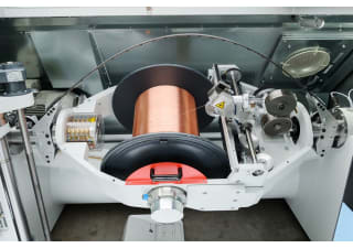
During this phase, wires are continuously twisted around a common longitudinal axis, with simultaneous longitudinal movement in one direction under coordinated parameters. This process creates uniformly structured, flexible, and stable wire assemblies called bunches. The machine commonly used in this process is a double twist buncher. After being pulled off spools from pay-offs installed outside the machines, the wires run through the ceramic openings of a plate mounted in front of the buncher and converge concentrically at one point. Here the wire bundle is turned once around its axis and directed through a nipple or die whose bore profile ensures that each wire adopts its assigned position in the assembly. Then the wire bundle passes over a guide roller into a semi-circular rotor bow which is continuously rotating around a take-up spool. The rotational movement of the bow and the movement of the wire bundle, induced by a capstan, result in the “first twist” of the wire bundle. When leaving the bow, the wire bundle is directed over a further guide roller to a spool carrier and finally wound up onto the take-up spool. This is when the “second twist” happens and the bunch is created. The rotor speed and pull-off speed are decisive for the lay length, i.e. the measurable length in the axial direction in which an element of the assembly turns once around the axis. Working speed is measured in lays per minute and known as the lay rate. The product of lay rate and lay length is equal to the production output.
Key parameters of this process are:
1. the forces acting on the wires and bunches;
2. the tension produced in the wire as a result;
3. the consistency of lay length;
4. the strain loss;
5. the concentricity of the bunch.
Next step: insulation
The following phase is insulation, in which a coating of insulating material is applied to the conductor by a high-temperature extrusion process. Then, several insulated wires are combined in a process called “stranding”.
The stranding technology

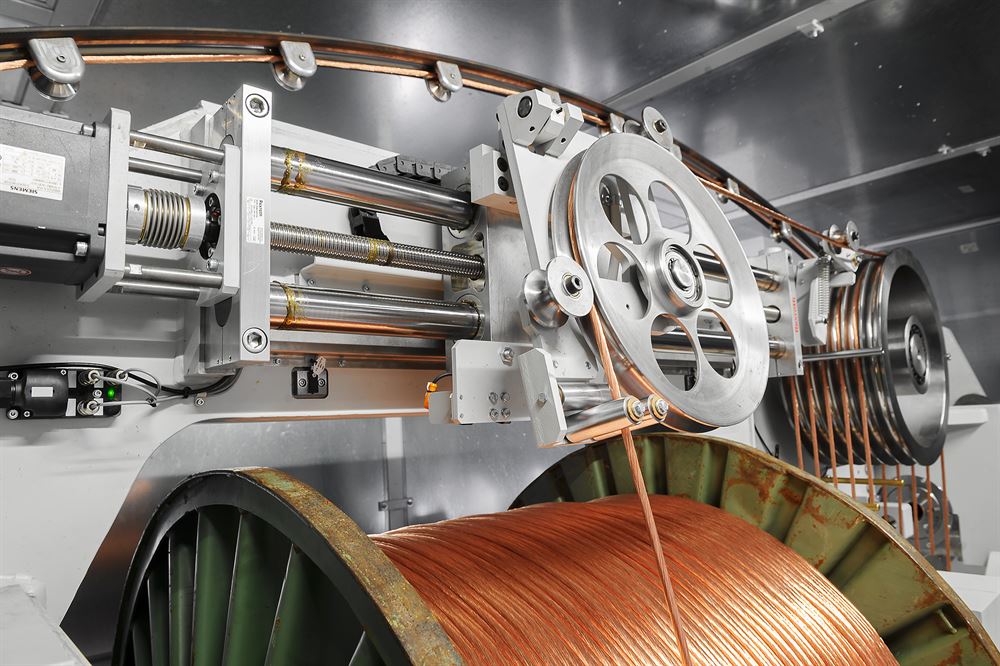
Interior of the D 1252 double twist stranding machine
Source: Image courtesy of Maschinenfabrik Niehoff
When stranding data and special cables, at first two insulated wires - often together with other elements such as a shielding foil - are helically stranded (“twisted”) to form a pair. For the subsequent step, which is the main stranding operation, four of these pairs are drawn off from their spools by powered and dancer-controlled pay-offs, and conveyed to one point of the stranding machine called “stranding point”. Before entering the machine, the pairs can be covered with an insulating foil, a shielding foil, and other elements, or whatever else is required for the given cable design. The final symmetrical cable can be directed straight to an extrusion line or a braiding machine. A big plus of double twist stranding machines is also their high production speeds.
For the manufacture of cross lay formations or cables requiring a greater number of conductors, more specific machinery is required, such as rigid stranding machines. Each of these machines features several cages which contain a certain number of bobbins, radially placed around the common longitudinal axis. Each cage rotates on its axis independently of the other cages in speed and direction. At the end of the stranding line, a big pulling capstan is used to pull the stranded conductors, while a take-up winds them onto spools.
Screening and armoring
At times, electrical cables may require further elements, such as armor, to protect cables from external damages and screens to insulate the signals that circulate in the cable from external interference. Screening and armoring are carried out by covering the cable with concentric tubular sheaths. Another operation sometimes necessary for cable protection is braiding. The braiding process is carried out by a braiding machine.
Braiding machines
Braiding machines for the manufacture of electrical cables can be subdivided into two categories: vertically and horizontally oriented machines. In the first case, the product to be braided is taken up in a vertical direction above the machine. In the second case, production is carried out parallel to the floor; large stiff braided cables can be produced in this way. Typical braiding materials are bare or plated round or flat wires made from copper, aluminium or stainless steel, as well as artificial yarn and fibers. The working principle is based on complex movements of the spool carriers on which the braiding bobbins are mounted and on the path of the braiding materials to be interlaced around the moving cable.
Modern braiding machines feature an infinitely adjustable electronic control of line speed and braiding pitch, as well as an automatic central lubrication system. In addition to the braid, sometimes a foil jacket is to be applied to increase shielding and durability of the braided cable. If the braiding machine is equipped with an integral taping device, both processes can be performed in one working step. The advantages are space savings, elimination of rewinding processes and an increase in product quality. Modern braiding machines with incorporated electronic controls can operate for many hours or even days without the intervention of an operator.
Cable sheathing
Electrical cables, at the end of the whole working process, may need an outer protective covering called “sheath” that can be made from polymers, rubber or lead and is applied like the insulation by an extrusion process at high temperature.
Literature
William A. Thue (ed.): Electrical Power Cable Engineering.
CRC Press, December 2011 (3rd edition)
ISBN-10: 1439856435
ISBN-13: 978-1439856437
The Wire and Cable Technical Information Handbook.(https://electrical-engineering-portal.com/download-center/books-%20and-guides/electrical-engineering/wire-cable-technical)
Power Cables Theory and Their Manufacturing Procedures (http://www.cablesbook.com/pages/cdownload.html)
Cable Designers Guide (http://www.nationalwire.com/pdf/cat07_design_guideV10.pdf)
Engineering Design Handbook: Electrical Wire and Cable
Publishing house: Book for Business, April 2002
ISBN-13: 978-0894991622
ISBN-10: 0894991620
Martin Herzog: Process analysis of double-twist bunching.
Production of flexible copper strands for cable manufacturing.
Manual for machine operators and instructors. 3rd supplemented edition, January 2018
ISBN 978-3-00-048932-7
Price: 98 € plus shipping (shipment DHL),
(Shipment against prepayment)
Mail-order: [email protected]
The information has been compiled by Dipl.-Ing. Konrad Dengler, technical journalist and translator specialized in industrial topics.